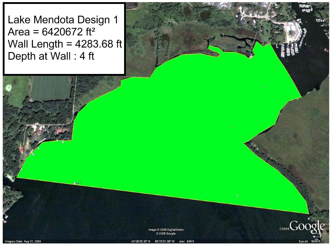
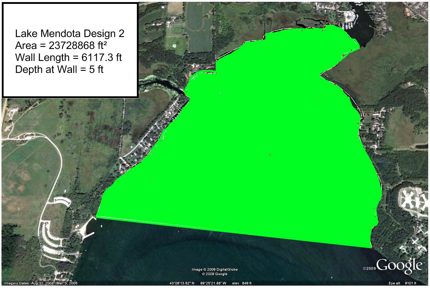
Proposed Designs
|
|
Water Year |
Suspended Sediment Tons/day |
Average Discharge ft³/sec |
Phosphorus Discharge lbs/day |
|
2003 |
2.96 |
45.3 |
30.14 |
|
2004 |
|
77.2 |
|
|
2005 |
|
60 |
|
|
2006 |
|
53.1 |
|
|
2007 |
|
82.8 |
|
|
2008 |
|
136.7 |
|
Table 1:
Average discharge per year of the
Since 2002, the largest recorded stream flow was 1,450 ft³/sec on June 9, 2008
Cross-sectional area of the
68.4 feet long by 9.5 feet deep = 649.7 ft²
A better
Lake
Mendota Limnological Information
30 inches
*Determined via limnology information above
Design Options
Design #1
Yahara
Total Algae Farming Area
= 27,646,597 ft²
Water Discharge
1) Yahara River
Houses and Businesses Directly Effected
6
40 Houses
Design #2
Yahara
Total Algae Farming Area
= 44,954,793 ft²
Water Discharge
1) Yahara River
2) Dorn Creek
Houses and Businesses Directly Effected
6 Marinas
78 Houses
Potential
Wall Design
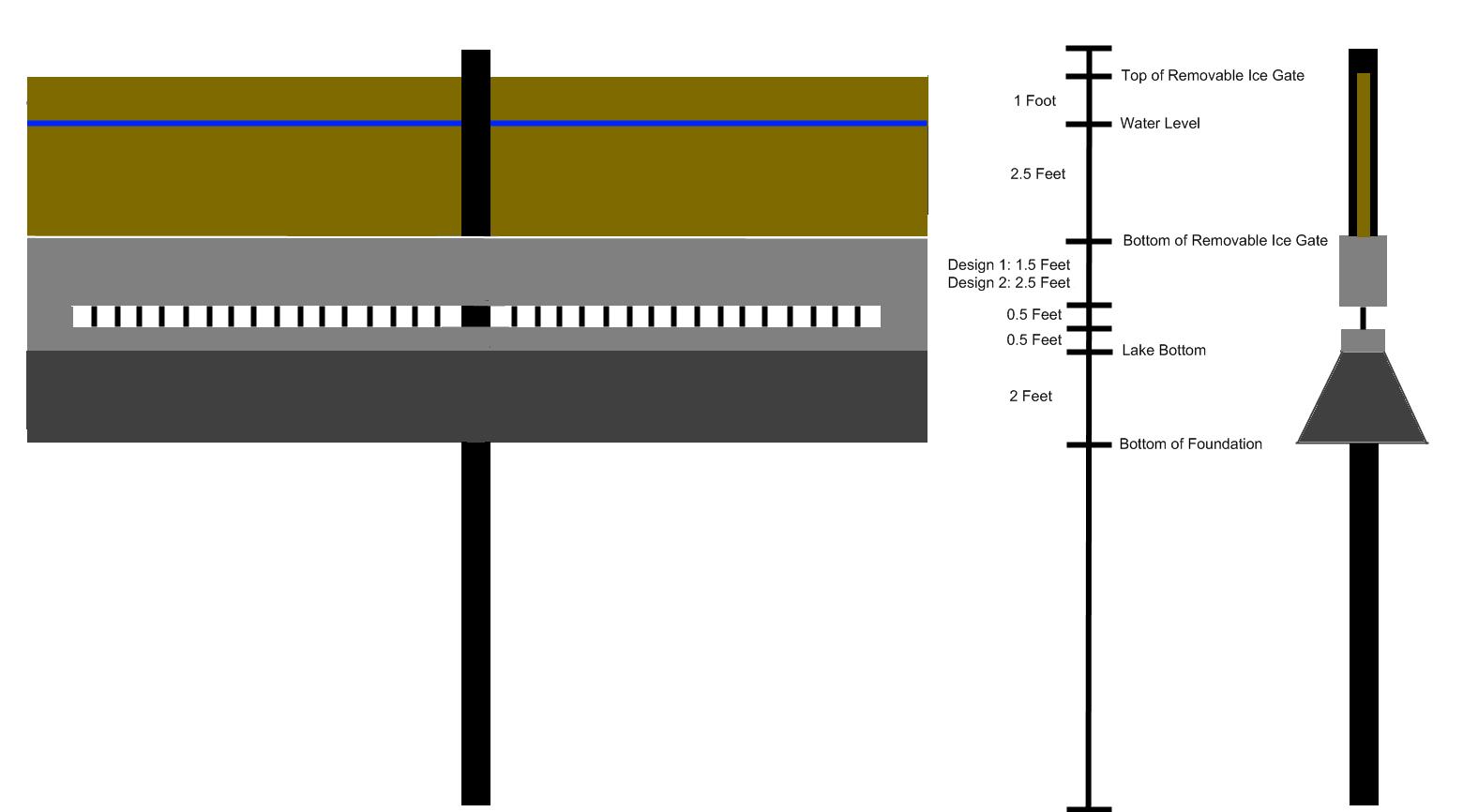
In order to retain the algae in the farm and allow water to be discharged we have designed the following retaining structure. The structure will consist of 20 foot segments that will be connected together to form a wall across the lake.
Starting from the bottom, each segment has the following features:
1) Each section will be anchored by a pile which will serve as the hinge for the rotating ice gate.
2) Each section will have a 2 foot wide concrete base that is to be buried below the lake bottom.
3) Above the concrete base is a concrete wall that begins at the bottom of the lake. Six inches above the lake bottom there is a six inch gap (with rebar gating) to allow for water to be discharged without algae. Above the gap is more concrete wall, either 1.5 feet for Design #1 or 2.5 feet for Design #2. The discharge gate for either design is much larger than the river inputs into the system, thus water should able to leave the algae farm and prevent flooding. Modeling will be done to help demonstrate this.
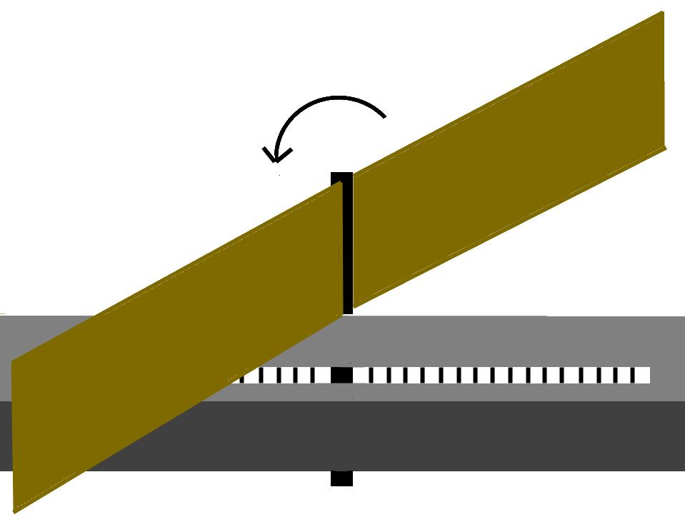
4) Above the concrete wall is a 3.5 feet high removable wall piece that is centered on the piling post. This removable piece will be removed during the winter to prevent ice damage to the wall. It sits 2.5 feet below the water level and 1 foot above. This piece is designed to rotate around the pile and can be open in times of flooding in order allow extra water to flow past the wall and prevent flooding in the area.
Cross Sectional Flow
Areas
Yahara
Six Mile Creek = 216 ft²
Design 1, 6” gap: 2,141.84 ft²
Design 2, 6” gap: 3,058.65 ft²
Design 1, ice gate open + 6” gap:12,851.04 ft²
Design 2, ice gate open + 6” gap:13,767.85 ft²
Wall Design Drawings