I began this project with the intention of producing water waves in a 24 in wide by 18 ft long flume, and soon found I knew little of the process. Initial designs included a downward chopping wave, but the design was discarded due to lack of reliable wave production.
With new design ideas, I researched forms of linear motion, including linear actuators, linear motors, and pneumatic pistons. Many of these systems either lacked the power or control to be a suitable solution; or were cost-prohibitive. In particular, linear actuators represented a cost-effective solution, but I found that the speed of motion of these actuators was directly related to the inverse of the resistant forces, which in the case of variable dynamic and hydrostatic forces, would cause irregular motion.
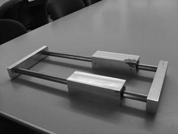
Figure 1: Secondary Design |
The secondary design (see Figure 1) utilized twin bearing blocks; each containing a pair of linear bearings. I found issues with this design as well, the wide stance of steel rods allowed a possibility of bearing freeze if the driving force was even slightly out of axial alignment. The guidance system also only allowed a total of 10 inch displacement, unacceptable considering displacement from the mean was limited to 5 inches. |
While coming up with design parameters for required torque, I found that it was inefficient to be accelerating the heavy steel rods, and also worried about moments in the system at full extension. All of these considerations would be important in the next design iteration. |
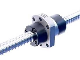
Figure 2: Ball Screw (GlobalSpec) |
After researching various forms of converting rotational motion into linear travel (a true linear motor was found to be out of our price range), I decided that a ball screw would be the most efficient and compact way of achieving our goals (see Figure 2). I found that a dual bearing ball screw could convert the motor's rotational power into axial motion with only 10% loss. The ball screw for the project had linear travel of 16mm per rotation, a mean diameter of 16mm, and a total length of .75m. |
With motor selection, I paired the working range of rotation with the a ball screw of the ideal pitch (equating to amount of linear travel due to a single angular rotation of the screw). The ball screw allowed us to achieve a much greater range of motion when compared to previous designs. |
By using the ball screw as a parameter for the remaining design, I came up with a modified linear slide table, powered by an end-mounted motor. The new design would incorporate the same linear bearings from the secondary design, but motion would occur only with rotation in the screw and motion of the two bearing mounts. This new design allowed me to minimize the inertial effects of rapidly accelerating the system's mass, and allowed us to reduce motor cost. With the design complete, I mathematically estimated peak torque requirements (including frictional loss, system inertia, hydrostatic forces, and dynamic fluid forces) to find the required motor power. The result was a 1kW DC brushless servo motor with an angular speed range of 0-5000rpms. The working range of the motor was specified to be 0-3000rpms, where very little change in torque was observed. The motor chosen had the resolution of 2,500 divisions per revolution, allowing precise movement. The motor also had very little inertia resulting in an efficient system of motion. With all components incorporated into a final design (see Figure 3), the motor and control system were purchased and construction began.
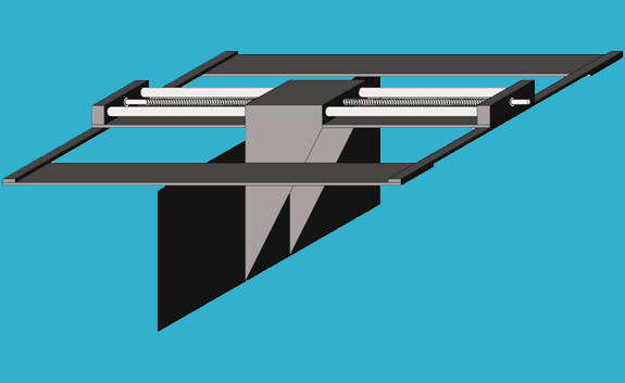
Figure 3: Isometric View of Wave Generation Device Jordan Read (2006) |
