
--
Project
Objectives and Motivations
--
--
--
--
--
Technical Background
Submerged
Breakwater
Artificial reefs are used as submerged breakwaters to reduce shoreline erosion. As shown in Figure 1, these reefs are manmade structures placed below the mean water level altering the wave's motion of fluids, known as hydrodynamics. Submerged breakwaters allow the waves to pass over them, instead of blocking them. Although these sound similar to the emergent breakwaters, a submerged breakwater does not jut out from the water. After the waves pass over the structure the wave height is decreased by a certain amount, depending on the design. By decreasing the wave height, the wave energy decreases, allowing the sediments to drop out of suspension.
Artificial reefs are used as submerged breakwaters to reduce shoreline erosion. As shown in Figure 1, these reefs are manmade structures placed below the mean water level altering the wave's motion of fluids, known as hydrodynamics. Submerged breakwaters allow the waves to pass over them, instead of blocking them. Although these sound similar to the emergent breakwaters, a submerged breakwater does not jut out from the water. After the waves pass over the structure the wave height is decreased by a certain amount, depending on the design. By decreasing the wave height, the wave energy decreases, allowing the sediments to drop out of suspension.
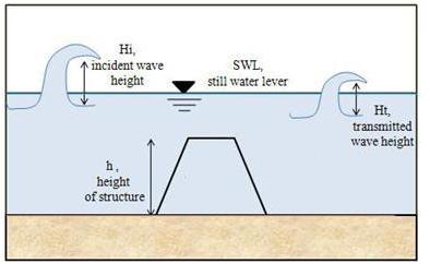
Figure 1: A submerged breakwater affecting wave height
by decreasing the incident wave height, Hi to a smaller
wave height, Ht (Anouil,
2008)
Wave Transmission
As mentioned in the Project Motivations, Artificial reefs act as submerged breakwaters causing energy from the waves to dissipate as they travel inshore. When waves have less energy, sand drops out of suspension causing either shoreline stabilization or accretion, which is simply sand building up along the shore.
Wave transmission is the
amount of energy that passes through by overtopping or traveling
through the structure (Breakwater Terminology). An effective
submerged breakwater does not allow too much energy to pass through the
structure, it's goal is to create wave attenuation, which is a loss in
energy. The following equation measures the effectiveness in
breaking wave energy.

Equation
1
Equation 1 shows the
relation of wave
transmission resulting from a submerged structure. Ht represents the
height of
the wave after it passes the breakwater at a certain point. Hc
represents what the
wave height, at the same point, would be if the submerged breakwater
was not
there.
Kt symbolizes
the wave transmission coefficient. The greater this value, the less
wave energy is attenuated. According to the
Friebel and Harris method, without storm surge, a 60%
reduction in wave height is required for effective shoreline
stabilization. Equation 2 depicts
what an effective wave transmission coefficient is for hollow
hemispherical shaped artificial reefs (HSAR). This equation can be used
to model Reef BallsTM.
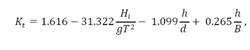
Equation 2
Hi/gT2 is the wave steepness, h/d is the submerged depth, and h/b is reef poration. This equation applies when Hi/gT2 is between the range of .0015-.015, h/d is within .7-1, and h/b is within .35-.583.
Energy Density
The sum of the kinetic and potential energies equates to the total energy, as shown in equation 3. The kinetic energy, Ek, of a wave is due to the velocity of the water particles responsible for wave propagation. Potential energy,Ep, from a wave is the energy results from the mass of water that is above the still water level.
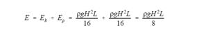
Equation 3
In order to get an energy density, which is
the total energy per unit area, the total energy is divided by the
length (Equation 4).
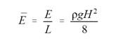
Equation 4
Equation 4
Equation 4 is a function of the wave height, H, with density, p, and
gravitational acceleration, g, as constants.