

1. Density and Water Content Tests
The Shelby tube samples were cut into 1 inch slices, and the sediment within that slice was weighed. This wet weight was used with the measured volume of the slice to determine the density of the material. The material was then put into the oven to dry in order to determine the water content. This analysis was performed on three different cores from locations inside and outside of the exclosure.
(a) (b)
Figure 6. (a) Paul cutting the Shelby tube into 1 inch slices. (b) Kevin weighing the cut sample
2. Erosion Test
The Shelby tube was inserted into a recirculation flume and the sample surface was exposed level with the flume bottom. A pump was used to create a flow in the flume, which was increased until erosion was visible. The velocity of the flow was used to calculate the critical shear stress for the sediments. The erosion test was performed on 2 different cores from inside of the exclosure.


(a) (b)
Figure 7. (a) The flume used for the erosion test. (b) The bottom of the flume with sediment visible after erosion.
3. Time Domain Reflectometry (TDR)
Time domain reflectometry uses electromagnetic waves to determine the dielectric constant of the sediment, which can be related to the volumetric water content. The electromagnetic wave is sent along 2 probes into the sediment sample. When the signal encounters a media with different impedance the wave will be reflected back to the source. The travel time of this reflected wave is used to determine the wave velocity in the sediment, which can then be used to determine the dielectric constant.

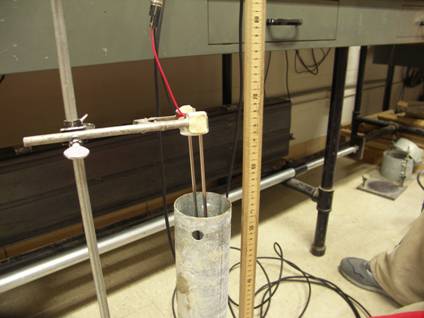
(a) (b)
Figure 8. (a) The TDR probe inserted into sediment sample (b) The data obtained from TDR for one sample.
![]()