Methods
The following picture illustrates how to measure the
reflection coefficient. By plotting the highest and lowest surface
elevations for each point, an envelope for the incident and
reflected waves is obtained. The top part represents total
reflection which creates a standing wave. In this case the Hmin
value is zero and Kr = Hmax/Hmax = 1 (a maximum). In the normal
case, Kr does not equal one, so measurements must be taken at both
the maximum and minimum heights.
(Coastal Engineering Manual, 2004)
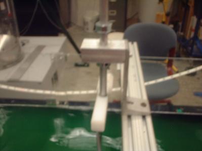
Our approach uses two sensors operating in a wave tank. The tank
has a paddle at one end which makes waves at variable frequency and
amplitude. The sensors were placed one at Hmin and one at Hmax for
each trial. We had to move the sensors to several different places
to find the Hmin and Hmax locations. The sensors are calibrated for
the depth of the tank and the conversion from the electronic signal
into distance.
The wave maker paddle settings as well as the water depth were set
at constant values for all trials (amplitude = .4, frequency = .91
hz, depth = 8 in). On the opposite end of the tank we placed a
plywood board to reflect the waves. For separate trials we tried
varying the reflection coefficient by changing the slope of the
board, and then running the experiment again using hoarse hair on
the surface of the board to increase porosity and surface roughness.