Hydropower
Generation in the Florida
Keys
By: Joe Pritzkow
B.S. Civil
Engineering
University
of Wisconsin-Madison
|
|
|
|
|
|
|

Since 1975,
oil demand in the world has increased from roughly 22 million barrels
per
day to its current 77 million barrels per day. At this current rate of
consumption, oil reserves would be depleted by the year 2048, since the
world’s total oil reserves are estimated to be around 1225 billion
barrels
(BP Statistical Review, 2003). Given the projected rate of consumption,
however, these reserves could be diminished by as early as 2042
(International
Energy Agency, 2003). In order to protect these oil reserves, an
alternative
source of energy needs to be implemented soon, or the world will be
facing
an energy crisis in the near future.
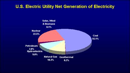
Hydropower
is a clean, renewable, and reliable energy source which can help reduce
oil demand and the resulting pollution. Below is a pie chart from March
of 2001 showing the
|
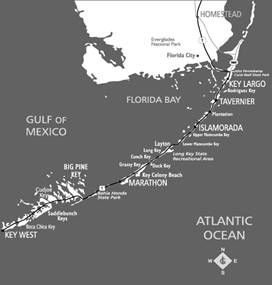
This project focuses on the
feasibility
of producing hydropower in the
In order to determine the
feasibility
of producing hydropower in the
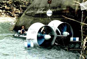
Once the turbines are set in
place,
they will be attached to a generator. In order to reduce the height of
the turbines above the ocean floor, the generator will be located below
the turbines under the ocean floor. The generator is the device that is
used to convert the mechanical energy of the rotating turbines caused
by
the moving water, into electrical energy. Below is a schematic of how
the
generator converts mechanical energy into electrical energy.
|
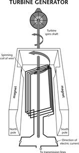
The force of the flowing
water
will cause the turbines to rotate. As they rotate, this rotation is
transferred
to a shaft which travels down to the generator. The generator is based
on the principle of “electromagnetic induction”, discovered in 1831 by
British scientist Michael Faraday. The principle of electromagnetic
induction
is this: if an electric conductor, like a copper wire, is moved through
a magnetic field, electric current will be induced, or begin to flow,
in
the conductor. This is because the magnet causes the electrons in the
electrical
conductor to transfer position throughout the conductor. The movement
of
electrons is defined as electricity. So the rotating shaft is connected
to copper coils inside the generator, and surrounded by a large magnet
to create a strong magnetic field. This creates an electric current,
which
can then be transferred to transmission lines. For the purposed of this
design, the transmission lines will run below the ocean floor to reduce
the risk of corrosion and damage. The transmission lines will then
carry
the electrical energy, harnessed from the generator in the form of
alternating
current (AC), to a transformer located on land. The transformer will
then
transform the alternating current to a higher voltage current which can
then be used for residential and industrial uses.
Now that the general concept
of
how electricity will be produced from the underwater current is
understood,
we must analyze the important design parameters that must be
established
to optimize the design.
1)The
correct location must be chosen. The reason for this is because the
amount
of electricity produced is directly proportional to the speed of
rotation
of the turbines. The speed of rotation of the turbines is directly
proportional
to the velocity of the water. Therefore, the locations where the
underwater
velocity is a maximum are optimal. Below is a map showing the
Earth’s centrifugal force
and
the gravitational attraction forces due to earth, the moon, the sun,
and
other planets, produces tides, or the periodic rise and fall of water
levels.
There are two types of tides, high tides, or flood tides, when water
flows
in from the ocean, and low tides, or ebb tides, when water flows away
from
shore and back out into the ocean. Additional monthly and annual lunar
cycles vary the strength of these currents. The Keys are a unique
situation
though, because the incoming water due to flood tides doesn’t want to
stop
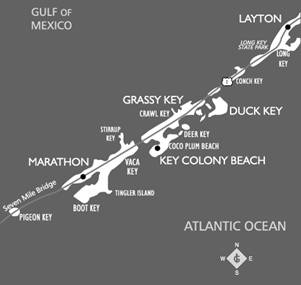
at the Keys, but rather, wants to flow through them and into the
Possible
Locations
One advantage of this type
of
hydropower is that it is a very reliable energy source. This is because
the energy source is independent of weather and climate change, as it
follows
the predictable relationship of the lunar orbit, which is known many
years
in advance.
2) The
optimum location must be chosen in term of depth. That is because if
you
are too deep, the underwater velocity is lower. Conversely, if you are
too shallow, while you have a much higher water velocity, you risk
damage
to boats. Based on the relationship between water depth and water
velocity,
it was determined that a depth of 10 meters would be sufficient to
provide
enough underwater velocity for electrical generation and provide enough
clearance for ongoing vessels.
3) The optimum size of the propellers on the turbines must be selected. This parameter is partially restricted due to the available depth before the turbines will interfere with vessels on the surface. For the purposes of this design, it was assumed that the propeller size would be 4 feet, making the overall size of the turbine approximately 8.4 feet.
4) The
angle of the incoming and outgoing current must be determined for
optimal
placement of the turbines. The goal here is to place the turbines at a
90° angle to the direction of water flow. To simplify this
analysis,
since the location of the turbines will be in gaps between adjacent
keys,
it can be assumed that the water will be coming in at a 90° angle
if
the turbines are parallel to the adjacent land.
5) Screens
must be used on the turbines to avoid harm to aquatic species and
humans.
Since many of the areas these turbines would be located in are home to
aquatic wildlife, the correct safety precautions must be taken. These
areas
are also home to many lobster hunters and scuba divers, and these
screens
would help reduce the risk of the turbines to humans.
6) Corrosion
resistant materials must be used for the turbines and generators. This
is because metals corrode in the presence of saltwater. Alternative
non-corrosive
materials must be chosen such as Superferritic Stainless Steels and
Nickel
Base Alloys.
Now that an understanding
has
been developed as to what type of system will be used and analyzed,
calculations
can be conducted to determine if the proposed design is feasible.
First,
properties of the water must be determined. If a proposed depth of 10
meters
is used as the location of the turbines, we can determine if the water
is shallow, deep, or intermediate. This is done by calculating d/L,
with
L being the wavelength. Based on data from the Florida Keys Weather
Service,
the average wavelength was assumed to be 37 meters. This yields a d/L
value
of 0.27, classifying the water as intermediate water.
To calculate the underwater
velocity,
the intermediate wave velocity equation can be used. This equation is
shown
below:
u=?Hcoshk(z+d)cos(kx-wt)/Tsinhkd
H=wave height=2ak=wave
number=2?/Lw=angular
frequency=2?/TT=wave
period
Based on this equation, the
underwater
velocity, u, equates to 0.327 m/s during normal flow. This number was
verified
using the Delaware Wave Calculator. However, this u value doesn’t
represent
the underwater velocity during peak conditions, when peak tides occur.
There is no equation to calculate the underwater velocity for this
phenomenon.
Therefore, an assumption must be made. To determine the underwater
velocity
during peak tides, it was assumed that the underwater current behaves
similar
to that of rip currents. This assumption was made based on personal
experience
I have had with both rip currents in
Now that we know the
underwater
velocities, we must determine the power that can be generated based on
these velocities. To do this, we will apply the wave power equation for
hydropower generation:
MW = Q*h*e/11.81
Q=flow (1000 ft/sec)h=head
(ft)e=efficiency of turbine/generator
Typically, this equation is
used
to calculate the MW (megawatt) production of hydroelectric dams, which
is why the variable h is included. To use this equation for the
purposes
of this project, h will be assumed to be 24.4 feet.
e is the efficiency of the
turbine
and generator to convert the potential energy of the water into
electricity.
It is nearly impossible to develop a perfect model that converts 100%
of
the potential energy to electricity. Therefore, an efficiency value of
0.85, or 85%, will be used.
The flow, Q, can be
calculated
by multiplying the underwater velocity by the area of the turbines
through
which it will flow. During normal flow Q1 is equal to 0.0593
(1000 ft3/sec). During peak flow, however, Q2 is
equal to 0.238 (1000 ft3/sec). Now it must be determined how
long the underwater velocity represents peak conditions, and how long
it
represents normal conditions. Based on my experience in the area, I
assumed
that 86% of the day, conditions were normal. The other 16% of the day,
the conditions were peak. This produces the following power equation:
MW = 0.16(Q2*h*e/11.81)
+ .84(Q1*h*e/11.8) = 0.145 MW
This is equivalent to 145
kilowatts.
Now it must be determined if this quantity is significant enough to
the
Since there are so many Keys
in
the
It is important to note that
these
numbers are all rough estimations. Exact numbers are hard to determine
since there are so many variables such as the size of the copper coil
and
magnet in the generator, the resistance to rotation the turbine
propellers
exhibit, and the type of turbine used, to name a few.
Based on the calculations,
it
seems like hydropower is a feasible alternative energy source in
the