Rapidly Installed Breakwater (RIB) Systems
http://chl.wes.army.mil/research/projects/ribs/lotschal.htp
Introduction
Motivations
Objectives
Hard Structures
Soft Structures
Discussion
References
Constructed
by: Michael Dobling
The offloading of military vehicles is cancelled more than 50% of the time
due to incidental wave heights of over 5 feet1. The Department
of Defense requires that offloading of vehicles occur through a sea state 3
condition (5 foot waves), but problems with unloading begin to arise when wave
heights are greater than three feet and wave periods of six seconds. The
Navy often refers to the unloading problems with three foot waves as "the sea
state 3 problem."1 The postponing of these unloading operations can
be very detrimental to the war effort. Dr. Jimmy Fowler states that
"the problem has often been called a 'war stopper' by Army leaders." The U.S.
Army Research and Development Center, Coastal Hydraulics Laboratory in
Vicksburg, Mississippi, has been conducting research on Rapidly Installed
Breakwater (RIB) Systems since 1995. This results of this research have
been
Breakwater structures play a very important role in reducing shoreline and
protecting harbored ships from offshore waves. In our CEE 514 class this
semester, we discussed the different types of breakwaters and their importance The recent development of Rapidly
Installed Breakwater Systems was particularly interesting to me because I am an
active duty member of the United States Navy Civil Engineering Corp and may work
with them in the future.
The
RIBs must accomplish three main goals:
1. reduce incidental wave heights by 50% (SS3 to SS2)
2. have rapid deployment capability
3. require minimal maintenance (withstand SS5)
The research on RIB's first began in 1995, with scale model tests.1
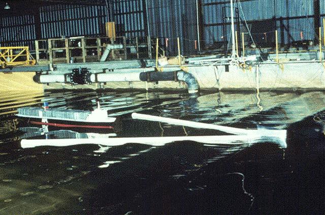
These tests can be seen in the Figure 1. The white v-shaped structure is
the breakwater and there is a model ship contained within the breakwater.
The results of the tests were very positive advancing the scope of the RIBs to
scale model testing in a real environment.
Figure 1. Scale Model Testing. [http://chl.wes.army.mil/research/projects/ribs/physmods.htp]
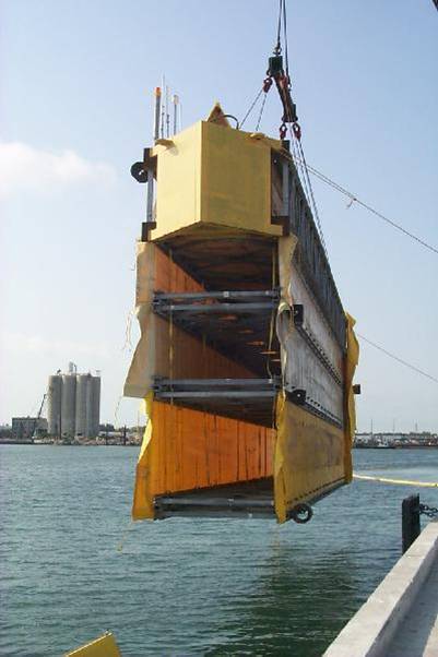
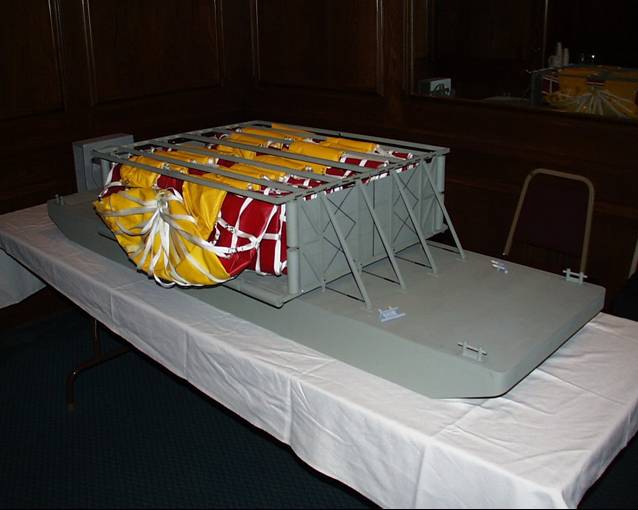
The next model to be tested was a rigid RIB seen in Figure 2. The
structure was triangular The XM - 99 was
the next RIB to be tested in the ocean. The XM - 99 was tested off the
coast of Cape Canaveral, Florida, from May 20, 1999 to June 04, 1999. The
XM - 99 was constructed in 250ft lengths that were 24ft high and 8ft wide, as
seen in Figure 4. The XM - 99 was said to represent a Venetian blind.
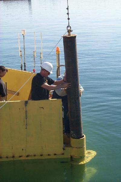
The deployment of the XM - 99 was successful and all performance objectives were
met. The only drawback was that the 250ft sections had to be connected
with a large pin; which was hard to put in place, see figure 5. One of the
lessons learned after testing the XM - 99 was that RIBs made of flexible
materials were much better than rigid RIBs. The XM - 99 was the last
"rigid" structure before the "soft" structures took over.
Figure 4
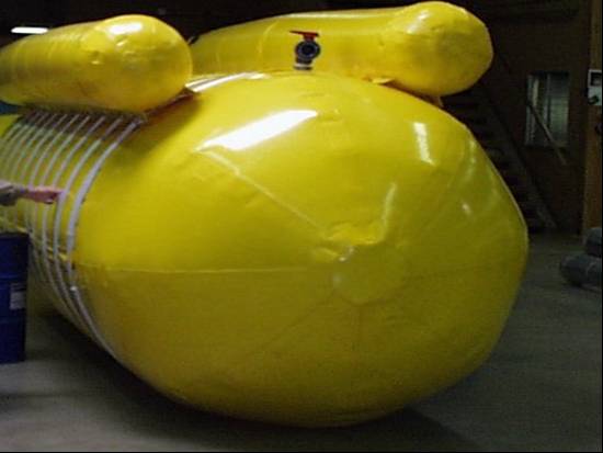
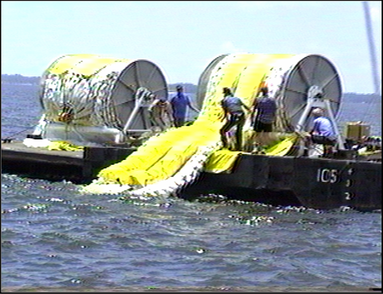
Figure 5 The first "soft" structured RIB was the Hydro RIB, the
structure of which is shown in figure 6. The Hydro RIB was
tested off the coast of Pensacola, FL in 1997. The Hydro RIB was wound
onto a spool (figure 7), much like wowing thread, and upon reaching the testing
site, unrolled into the ocean. Next, sea water was pumped into the main
chamber making the structure more rigid.
Figure 6
Figure 7 The testing of the Hydro RIB went very well, but there
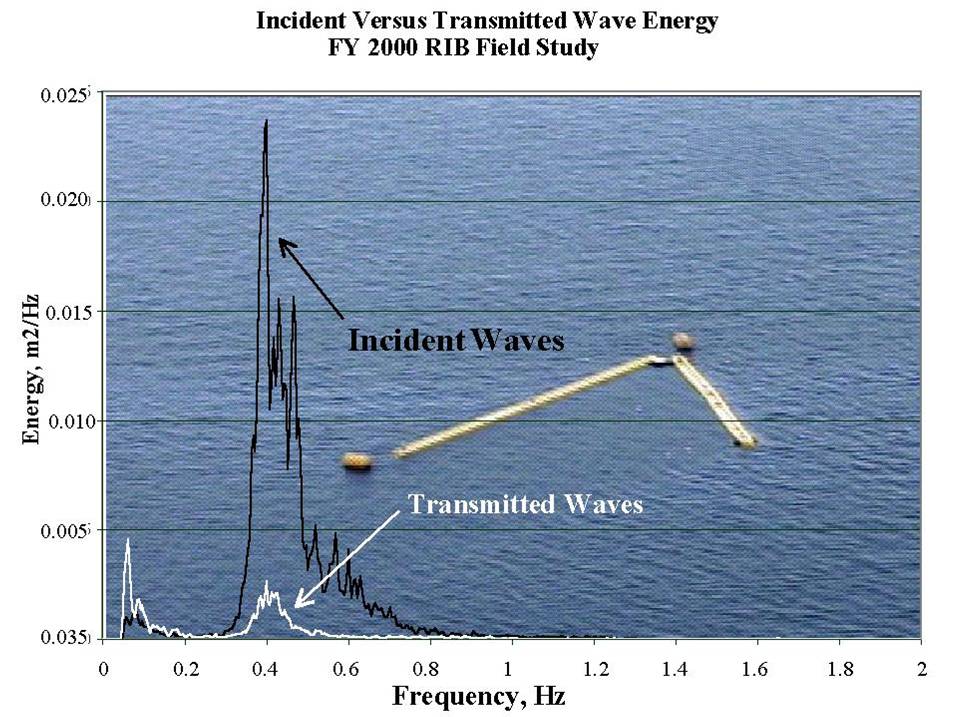
was still room for improvement. The XM 2000 was the next RIB built and
tested off the coast of Pensacola, Florida, for five weeks in the year 2000.
The structure of the XM 2000 was much like the Hydro RIB except more straps,
made of high-strength marine fabrics were added around the hull for increased
strength and the mooring system was changed. The new mooring system, the "Seaflex",
was made of reinforced energy absorbing elastometric cord. This new
mooring system increased the absorption load on the hull and allowed for an
increase in steeper angles mooring , saving space. . The XM
2000 was built in one quarter scale, with the bags six feet in diameter once
they were filled with sea water.1 The tests showed a dramatic
change between the incident wave energy and the transmitted wave energy, figure
8.
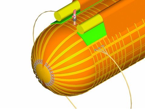
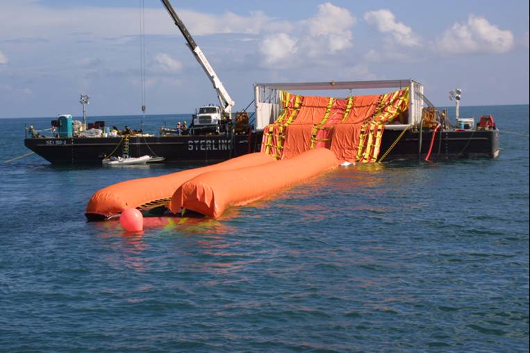
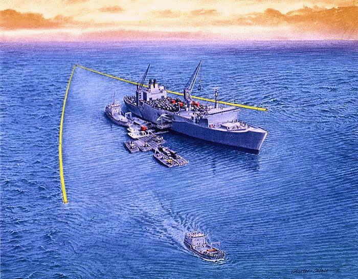
Following the XM 2000 was the XM 2001. The XM
2001 was tested at at full scale, the diameter of the hull was 28 feet and the
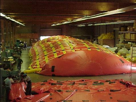
sections were 200 feet long (figure 9). Figure 10 is a picture of the XM
2001 during fabrication. During transportation the sections were
very compact, only requiring one flat bed semi trailer. The Kevlar webbing
around the hull was increased and a new method of RIB deployment was tested; a
model is shown in figure 11. The new deployment mechanisms resembles
an accordion when the RIB is stored. The new method of deployment,
shown in figure 12, was very successful, but recovery was a little more
difficult. The XM 2001 was also filled with sea water. The
improved pressure release valves, located on the top of the hull also performed
very well.
Figure 9
Figure 10
Figure 11
Figure 12
The testing of the RIBs has returned excellent results and future testing
should be continued. According to Dr. Jimmy
Fowler, "every RIB we tested in the field has reduced the waves in the Sea
State 3 by 50 percent or more; the RIB-XM 2000 actually reduced some waves
by about 70 percent.1 The optimal design has almost been found, the
only design change left is to optimize the joint connecting the two arms of the
V-shape.1 The transportability and hull strength are two other
design characteristics that need to be examined.1
The rapidly installed breakwater systems may not
only find a place in the military, but may also be commercialized. The
RIBs could be used as temporary breakwaters making the installation of a more
permanent breakwaters easier. They could also be used in rescue operations
for aircraft crashes or vessel recovery operations. 1 1. U.S.
Army Corp of Engineers. Engineer Update. March 2001, vol. 25, no. 3.
retrieved from
http://www.hq.usace.army.mil/cepa/pubs/mar01/story9.htm
2.
http://chl.wes.army.mil/research/projects/ribs/
3.
Melby et al. A Nearshore Rapidly-Installed Breakwater for
Military Force Projection and Sustainment Operations.
4. Dr. Larry Fowler's presentation, Rapidly Installed
Breakwater Update, at the R&D Symposium: Joint Logistics Over-the -Shore and
Logistics From the Sea. The
presentation was given on January 30, 2002.
5. Dr. Larry Fowler's presentation, RIB/ATD Update, at
the R&D Symposium: Joint Logistics Over-the -Shore and Logistics From the Sea.
The presentation was given on January 31, 2001.
6. Dr. Larry Fowler's presentation, RIBs Update/ATD
Update, at the R&D Symposium: Joint Logistics Over-the -Shore and Logistics From
the Sea. The presentation was given on February 2, 2000.
University
of Wisconsin-Madison
Department
of Civil and Environmental Engineering
CEE
514: Coastal Engineering
Professor
Chin Wu
Fall
Semester of 2003