By Keith Puro
CEE 514 : Coastal Engineering
Fall of 2001
 Introduction:
The
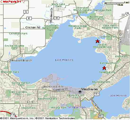
Tenney and Warner Park breakwaters (red stars) are located on Lake Mendota
in Madison, Wisconsin. In this report I will look at the existing
breakwaters to determine their structural stability and if they are meeting
the intended goals of their design.
Introduction:
The
Tenney and Warner Park breakwaters (red stars) are located on Lake Mendota
in Madison, Wisconsin. In this report I will look at the existing
breakwaters to determine their structural stability and if they are meeting
the intended goals of their design.
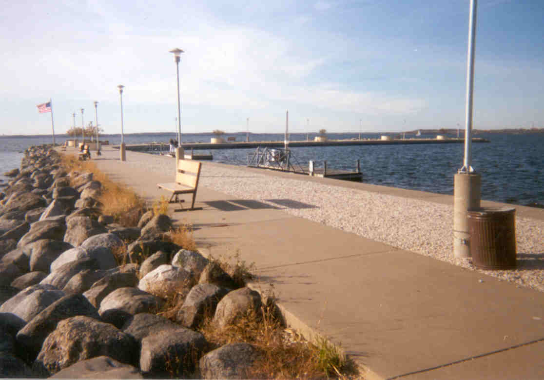
The Tenney Park breakwater protects the dam and locks that connect the lake to Lake Monona. The dam controls the water level of Lake Mendota, keeping it on average 5 feet higher than Lake Monona. The current concrete dam was built in 1959, although there has been a dam there since 1847, when an earthen structure was first built there. As far as the breakwater, according to Bill Bauer of the City of Madison the Tenney Master Plans by O.C. Simonds and John Nolen dated in the early 1900s show a shoreline protrusion in the location of the existing breakwater. The actual plans for any of the further construction cannot be located and are not known. The breakwater has a concrete path along its top and benches making it a popular place to go and relax out on the lake.
The Warner Park breakwater protects three floating docks
at the Warner Park boat launch. It was constructed in 1990 and designed
by Arnold and O'Sheridan, Inc. of Madison. Since it was constructed,
high water levels in 1993 and again in 2000 decimated the structure, causing
a significant amount of material lost from waves crashing into and
overtopping the structure. After 1993 18 inches of material was added
to bring the structure back up to a working elevation. Also, severe
settling of the soils under the structure have caused its height to diminish.
Geotextiles were placed underneath the structure during construction, but
have not been adequate in abating the settling. The electrical
service on the breakwater to the light posts has also been under constant
repair because of the settling. But despite all of this continuing
damage to the structure there is no maintenance budget, so material is
only added when extra material is available and the machinery is
available. Hence, the current structure is much different than the
one shown on the original construction plans. Incidentally, the city
wanted to construct a floating breakwater because of concerns with the
silt and sand material of the lake bed. However, the Wisconsin Department
of Natural Resources (WDNR) opposed a floating breakwater and would only
approve a rubble-fill design.
Dimensions: The breakwater at Tenney Park extends out from the shore 383 feet. It then turns 105 degrees and extends 343 feet. The width or breadth of the structure is 25 feet. It's height is 13.9 feet*. The lakeward side of the structure has a 13 degree slope.
At Warner Park the structure is nearly L-shaped, it extends 180 feet out into the lake with a slight angle about a third of the way out. The arm then extends parallel to the shore 120 feet from the base. Its breadth is 20 feet, its height is 12.3 feet*, and it has practically a vertical slope. There is some rubble in front of the armor units that make up the vertical slope, but they just scattered in front of the structure do not form a consistent layer that I could use in any calculations.
*Datum is 840 feet above sea level.
Approach: There were three
things I looked at for each structure. The first was to look at the height
of the actual structures and compare them to my calculations of the potential
wave run-up. Secondly, I looked at the stability of the armor units
(riprap) of the structures to determine if it was heavy enough to sustain
the forces imparted on them. And finally I calculated the diffracted
waves heights inside the harbors at the structures that the breakwaters
are built to protect.
1. Structure Height:When a structure is designed, its height is determined by calculating the design run-up plus freeboard on the structure. The run-up and freeboard are measurements of how high waves will go up onto a structure. For a given design lake level, the run-up plus freeboard should equal the height of the structure above the water surface. For this project I calculated what lake level each structure will give me those results and then compared that level with some historical data to see whether the structure is adequate.
To find run-up the first step is to find the significant wave height (Hs). The maximum fetch for both structures is 5.7 miles. I used a maximum land wind speed (UL) of 35 miles per hour, obtained from the Wind Atlas of Wisconsin. I converted that to a water surface wind speed (Uw) using the following equation that we used in class:
Uw = .71(UL)1.23
This gave me a design wind speed of 56 miles per hour. Then using the JONSWAP method and assuming a fetch limited case, I calculated the significant wave height (Hs) and the period (Tp).
F* = (g)(fetch)/(Uw)2
Hs* = .0016(F*)½
Hs = (Hs*)(Uw2)/g
Tp* = .286(F*)^(1/3)
Tp = (Tp*)(Uw)/g
From those equations I came up with a significant wave height of 4.0 feet and a period of 3.8 seconds. Also needed is the deep water wave length (Lo):
Lo = (g)(Tp2)/(2)(PI)
I got a deep water wave length of 75 feet. With those numbers I then used the Hunt and Walson equations to calculate the run-up (R). For the Tenney Park breakwater I used (where þ is the slope of the structure) the equation:
R/Hs = tan(þ)/(Hs/Lo)½
For the Warner Park Breakwater I used the Hunt and Walson equation for vertical walls:
R/Hs = sin(þ)/(Hs/Lo)½
But these calculations do not take into account the material that the waves are running up onto. So I calculated the reduced run-up (Rr) based on a rough slope run-up correction factor (r) of .6 for quarrystone, the material used for the armor stones at both locations:
Rr = (r)(R)
Finally I calculated the relative freeboard (R*m):
R*m = (R/Hs)[(Hs)(2)(PI)/(Lo)]½
The sum of the reduced run-up plus the relative freeboard
should then equal the height of the structure. I used a spreadsheet
to enter different water levels to see at what point that would happen.
| Structure | Max. Water Level (feet)* |
| Tenney Park | 12.1 |
| Warner Park | 7.2 |
|
Current
Lake Level (Dec. 2001)
|
9.6 |
The next graph shows the maximum water levels at which the structures won't be overtopped versus the maximum yearly water level. The maximum yearly water level was obtained from the United States Geological Survey's records of Lake Mendota.
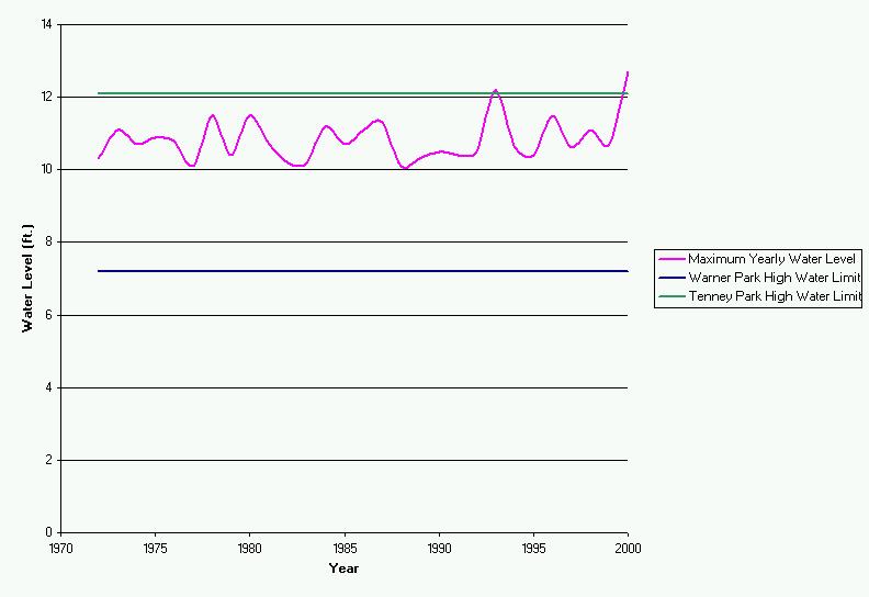
With the Tenney Park Breakwater, you can see that only during two high water levels that the structure could be susceptible to water overtopping it. This structure is sound and should not have any problems. But, you can see the current elevation of the Warner Park breakwater is susceptible to overtopping and thus loss of material. In fact the current elevation of the breakwater is 12.3 feet, so during the 2000 high water level, the water level was right at the top of the structure, any wind at all could cause waves that would do some damage to the structure.
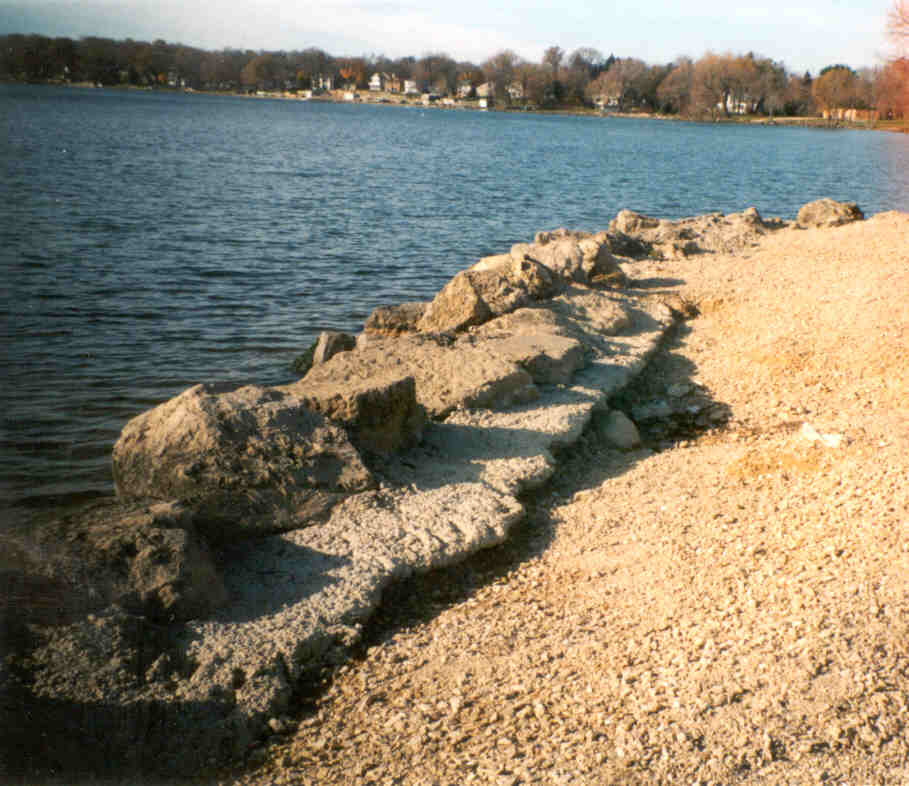
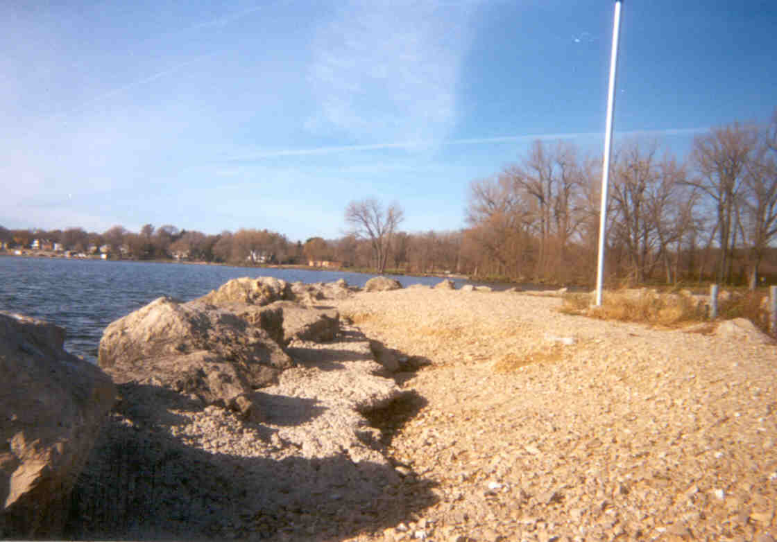
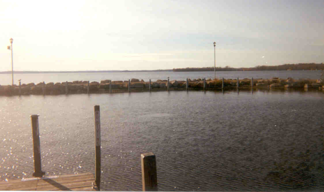
In these pictures you can see the affect the waves have had on the top of the structure. Large amounts of material have been washed off of the structure. The concrete has been placed to try and prevent any more material washing through the gaps between the riprap.
One of the major problems in calculating what the design height of a
structure in Lake Mendota is how to take into account all of the recent
development in its watershed. In 1993 and 2000, 100-year type lake
levels were seen. These high water levels could be more common in
the future. This is because with more development, there is more
surface runoff into the rivers that empty into Lake Mendota. This
water previously would have infiltrated into the ground or slowly made
its way into a river, but now that water is quickly routed to the rivers
causing all of the water from a storm to make its way to the lake quicker,
raising the lake level rapidly. Because of these recent high water
levels, it is difficult to know what to design for, just looking at the
historical data, one may not come up with an accurate 100-year (or whatever
year one would like) lake level to design for.
2. Armor Units: In the second part of my project I calculated the minimum required weight of the armor units (or riprap) using Hudson's formula. The formula is based on a balance to making sure each armor unit maintains stability under the forces caused by the waves.
W = [(û)(Hs)]/[(KD)(SG-1)3(cot(þ))] where:
W = median weight of armor unit û = unit weight of armor
KD = stability coefficient, 1.5 for smooth quarrystone SG = 2.65 for quarrystone þ = structure slope
|
|
|
|
|
|
|
|
|
|
|
Lower Layer = 4000 |
The Tenney Park breakwater had two distinguishable layers of armor units.
The lower layer easily meet the minimum requirement that I calculated.
I did not calculate what a minimum requirement for the upper layer of armor
units would be. It was difficult to calculate the weight for the
Warner Park breakwater because the Hudson formula does not work well for
vertical surfaces, so I used a slope of 75 to get a number, but I would
not put too much reliance in it. For both structures, it didn't appear
that the armor unit weight was a problem.
3. Diffracted Wave Heights in the Harbors: The purpose of these structures is to create safe harbors. To determine if this is the case, I looked at the heights of the diffracted waves in the harbor. To determine these wave heights, I had to look at the different directions the waves could possibly come from. For the Tenney Park Breakwater, I looked at four different directions that the waves could be coming from, and for Warner Park I looked at five. For each of these different angles, there is a different fetch (see tables below), causing different incoming wave heights.. I figured out the different heights using the same JONSWAP formula as above, and also calculated the period, and from that I also calculated the wave length. With that data I used the Wiegel tables method that we learned in class to calculate the diffracted wave heights. To use this formula I needed to know the distance (r) from the end of the breakwater to the part of the harbor that I wanted to find the wave height at. For Tenney Park I used the distance to the locks and for Warner Park I used the distance to the end of the closest dock. Those distances came out to 500 and 122 feet respectively. Also needed is the angle (B) formed by the arm of the structure and a straight line from the end of the structure to the point that I was measuring the wave height at. For Tenney Park I found an angle of 35 degrees and at Warner Park 80.5 degrees. I used a lake level of 9.8 feet, which has been the average lake level for the past 30 years.
Tenney Park
| Location on Opposite Side | Angle to Structure Arm | Fetch (miles) | Hs in Harbor (feet) |
| Pleasant Branch | 100 | 5.7 | 0.3 |
| Bishop Bay CC | 90 | 4.2 | 0.3 |
| Governor Nelson S.P. | 55 | 4.1 | 0.7 |
| Governor's Island | 45 | 2.5 | 0.9 |
Warner Park
| Location on Opposite Side | Angle to Structure Arm | Fetch (miles) | Hs in Harbor (feet) |
| Marshall Park | 105 | 5.7 | 1.0 |
| Spring Harbor | 90 | 5.4 | 1.4 |
| Second Point | 75 | 3.7 | 2.1 |
| University Bay | 67 | 4.0 | 3.3 |
| UW Campus | 60 | 3.5 | 3.3 |
From the data it can be seen that there are no sizable waves inside
the Tenney Park harbor. The structure does a good job of shielding the
locks and dams from potentially dangerous waves. At Warner Park there
are much higher waves inside the harbor. One of the main reasons
for this is because the arm of the breakwater does not stick out very far
relative to the floating dock. This means that the waves at Warner
Park that I am looking at are not being diffracted as much as the ones
at Tenney Park are, and hence they are higher. This can be seen by
comparing the angles (80.5 for Warner compared to 35 at Tenney) formed
by the breakwater and the point of concern. The bigger the angle
the less diffraction that will take place, and the higher the waves will
be.
Conclusion:Looking
at the calculations concerning the structure heights, armor unit sizes,
and diffraction; it is fairly obvious that Tenney Park structure is stable
and not in any danger with current lake levels. It also has very
small wave heights inside its harbor which shows that it is doing the job
it was designed to do. As for the Warner Park structure, it is obvious
that remediation is necessary. The problem is that there is no money
in which to do that with. Since the high water levels in 1993, the
structure has not looked like it was originally designed to. The
structure has virtually no slope, which causes material to easily wash
off of the structure when it is overtopped by waves. Also there is
only one layer of huge riprap that make up the bulk of the lakeward side
of the structure, as apposed to having many layers of riprap to take the
forces. This is not advantageous because if that layer were to fail
there is no other layer of riprap to protect the structure. It is
also easy to see that the elevation of the structure also needs to be increased.
At this current level the breakwater will be sustaining damage every time
there is a major storm. Also, the seaward arm of the structure could
be extended, that would help lessen the diffracted wave heights in the
harbor.
Thanks to:
Bill Bauer: Landscape Architect with the City of Madison Department of Public Works
Phil Keillor : Wisconsin Sea-Grant Coastal Engineer
Chin Wu, PhD.: University of Wisconsin-Madison Coastal Engineering Professor
Tim Santiago: Classmate/Riprap Measurer