Modeling
With RMA2 and SMS
Abstract
Introduction
Motivations
Objectives
Methods
Results
Discussion
Future
Goals
Personal
Note
References
Constructed
by: Jan Jacobson
University
of Wisconsin-Madison
Department
of Civil and Environmental Engineering
CEE
514: Coastal Engineering
Professor
Chin Wu
Fall
Semester of 2001
Abstract:
An
analysis of wind induced wave setup and circulation patterns is undertaken
with numerical modeling provided in the RMA2 package within the Surfacewater
Modeling Systems (SMS) software. Graphics are provided depicting changes
in water surface characteristics for associated changes in wind direction
for a given wind speed. Though this is the focus of the project RMA2 methodology
will also be discussed.
Introduction:
Circulation
patterns and wind induced setup in water bodies have been something of
intrigue in the hydrodynamics world for quite some time. Numerical models
have recently been implemented to help scientists and engineers better
understand these processes. RMA2 is one such model that is a two-dimensional
depth averaged finite element hydrodynamic numerical model. It computes
water surface elevations and horizontal velocity components for subcritical,
free surface flow in two-dimensional flow fields. Utilizing its calculations
of water surface elevation, depth, and two-dimensional velocity in the
horizontal plane a clearer picture of natural environments can be attained.
The practical attributes of these types of analyses stretch from evaluation
of existing coastal structures to tracking extremely sensitive transport
of water insoluble contaminants. Surfacewater Modeling Systems (SMS) provides
pre- and post processing for models like RMA2.
Motivations:
Between the two issues
of circulation patterns and wind induced setup, most notably storm surge,
an extrapolation can be made to most water quality and coastal engineering
problems. For example, ascertaining the magnitude of wind induced setup
is paramount in designing coastal structures. It is similar to the importance
of foundation design for high-rise buildings, with the foundation being
the storm surge and the building being the wave. Often times the public
perceives that the destructive mechanism in coastal environments is the
wave, but in reality, especially in oceanic coastal areas, storm surge
is the major culprit. Simply put, assuring a stable coastal area requires
understanding wind induced setup.
Some of the major issues requiring
understanding circulation patterns include retention time calculations
and contaminant transport. Retention time is loosely defined as the time
a particle of water spends in an impoundment. However, this calculation
is often times extrapolated to the time a contaminant particle spends in
a water body. This is typically a conservative estimate so understanding
circulation may lead to tracing a contaminants retention time with numerical
models. This, in turn, may help avoid over design for a given project.
The quantification of contaminant
transport is, in many ways, a more complicated problem, but it is an easier
problem to conceptualize. Scientists and engineers simply want to find
out what areas of a water body are more likely to see higher concentrations
of contaminants. These areas of higher concentrations are often times solely
due to the physics of the system, and surface water circulation patterns
can have a very significant contribution to the systems characteristics.
Objectives:
The
objective of this project is to observe how changes in wind and basin characteristics
affect both wind induced setup and circulation patterns in water bodies.
Methods:
RMA2 computes a finite
element solution of the Reynolds form of the Navier-Stokes equations for
turbulent flows. Friction is calculated with the Mannings or Chezy equation,
and eddy viscosity coefficients are used to define turbulence characteristics.
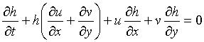
Both steady and unsteady state problems can be analyzed. To do this, the
model solves the depth integrated equations of fluid mass and momentum
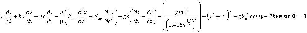
conservation in two horizontal directions. The conservation of mass is
seen as equation 1, and momentum conservation is seen in equations 2 and
3.
(1) 
(2) 
(3) 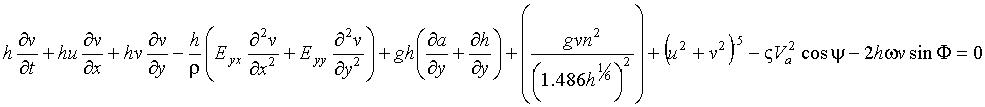
Table 1:Key to terms in equations
1 through 3
| x, y |
Cartesian directions |
|
u, v
|
velocities in the x and y directions,
respectively
|
|
h
|
water depth
|
|
a
|
bottom elevation
|
|
E
|
eddy viscosity coefficient
|
|
n
|
Manning's roughness coefficient
|
|
Va
|
Wind Speed
|
|
y
|
wind direction
|
|
w
|
Earths rotation
|

|
Wind Shear Coefficient
|
|
F
|
local latitude
|
In
looking at the factors seen in Table 1 it is clear that this model considers
setup due to Coriolis Force (w, F)
also, but for smaller inland lakes the primary driving force is wind.
The finite element method solves the mass and momentum equations using
the Galerkin Method of weighted residuals. The solution is fully implicit
and the set of equations is solved simultaneously by Newton-Raphson nonlinear
iteration. To better illustrate what this method of iteration entails a
quadratic function may be seen in figure 1. The idea is to find a solution
to the equation as close to the root as possible.
On
the x axis, x1 is
the initial guess at a value which will yield the optimum solution. The
solution with x1 is
the point marked initial solution. A line (tangent line 1) which is tangent
to the curve at this point is computed. The place where this line crosses
the x axis becomes x2;
the second guess used to solve the problem. A new solution is calculated
from x2, and another
tangent line (tangent line 2) is computed. The point where this tangent
line crosses the x axis becomes the next guess, x3.
And so on, until the difference in value along the x axis, between two
successive solutions, becomes less than the a pre-defined convergence criterion.
At this point, the solution has converged.
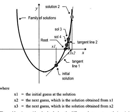
Figure 1: Iteration discussion from RMA2 literature.
Surfacewater
Modeling Systems (SMS) was chosen to meet the aforementioned objectives.
The software provides pre- and post processing for surface water modeling
and analysis. It includes two-dimensional finite element, two-dimensional
finite difference, three-dimensional finite element and one-dimensional
backwater modeling tools. It provides interfaces specifically designed
to facilitate the utilization of several numerical models. SMS can develop
profiles and cross section plots, two-dimensional vector plots, drogue
plots, color shaded contour plots, time variant curve plots, and dynamic
animation sequences from solution sets produced by RMA2.
Once
these very basic conceptualizations of the focus models have been sewn,
a general approach to understanding the manifestations of wind induced
setup and circulation patterns must be developed. To that end, a synthetic
lake was created. Lake Larry was created as a uniform depth basin with
rectangular dimensions. Though easy to envision it may be seen in figure
2.
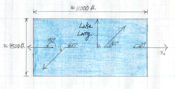
Figure 2: Lake Larry dimensions
and wind directions used in modeling process. All angles are referenced
to the positive x direction.
The reader may be questioning how
a basin such as this could ever be applied to an actual natural body of
water. One of the principle lessons learned during this process was that
in trying to utilize a numerical model the user must understand the way
the model handles the most basic of problems. So the analysis of Lake Larry
represents the first step in fully understanding RMA2.
In addition to the dimensions shown
in the figure other key parameters are the Mannings n value of 0.03 and
the eddy viscosity coefficient of 25. Though, clearly, the implementation
of an eddy coefficient is not necessary here it was done so as to stay
consistent with examples found in the SMS documentation.
In order to proceed boundary conditions
had to be established. To maintain a stable and stagnant water surface
these were set to 5 cfs of steady flow at the east and west ends of the
lake. The north and south boundaries are no flow. Once a still water surface
had been established, the wind could be introduced into the system. Five
different wind directions were analyzed while keeping the wind speed constant
to study the effects of a changing wind direction only. These directions
can be seen in figure 2. Setup calculations from RMA2 were then verified
with analytical techniques learned in Professor Wus Coastal Engineering
class. The method of choice was the non-linear storm surge technique. The
equation and associated components can be seen in equation 4.
(4) 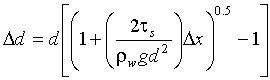
Where: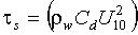
Table 2: Table describing
terms in equation 4.
|
d
|
water depth
|
|
rw
|
density of water
|
|
ts
|
surface shear stress due to
wind
|
|
g
|
gravity
|
|
Dx
|
wet distance over which the
wind blows
|
|
U10
|
wind speed
|
|
Cd
|
1.21E-6 if U10
is less than 5.6 m/s
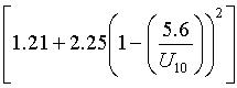 E-6
if U10 is greater
than 5.6 m/s E-6
if U10 is greater
than 5.6 m/s |
Results:
The following are plan
views of Lake Larry. Each view represents a different wind direction while
maintaining a wind velocity of 50 mph. The arrows on each diagram are created
by a grid representation of a two-dimensional velocity vector field. The
color coded contoured information represents water surface elevation. Please
disregard the upstream inflow (40000) and downstream head (20) displayed
on the figures. They are meaningless, and are not the true boundary conditions
for the actual model simulations.
Table 3: Expected
setup given wind direction as calculated with non-linear method
|
Wind Direction (° cc from positive x-axis)
|
Expected Setup (ft)
|
|
0
|
0.648
|
|
45
|
0.372
|
|
90
|
0.264
|
|
180
|
0.648
|
|
225
|
0.372
|
Wind direction equal to 0°
from the positive x-axis:
Wind direction equal to 45°
from the positive x-axis:
Wind direction equal to 90°
from the positive x-axis:
Wind direction equal to 180°
from the positive x-axis:

Wind direction equal to 225°
from the positive x-axis:
Discussion:
After observing the contour
mapping of the RMA2 simulations it seems quite reasonable to ascertain
that the model can predict wind induced setup. For all of the wind directions
the results are quite close to what were calculated with analytical techniques.
It seems, though, that the rest of the surface elevation shape is possibly
inaccurate. This is especially true when the wind direction is against
what the model perceives as the flow direction. For this study the upstream
and downstream flows were 5 cfs, an essentially negligible amount of flow.
This was thought to have provided a stagnant situation in which wind of
the same magnitude from the exact opposite direction would create the same
setup. This can be accomplished, but the surface water elevations from
the shore of the winds origin are obscenely small. As seen in the 180°
and 225° wind direction simulations these values are -8.5 and -2, respectively.
Discovering the reason for this unequal handling of, essentially, the same
wind direction must be understood before an accurate representation of
wind induced setup can be surmised.
The true value of the figures displayed
in the results section is the setup analysis. Though observing the circulation
patterns is a very useful tool, a transient (multiple time steps) solution
is more appropriate than the steady state solution shown here. Again, this
study represents a first step, and an understanding of the steady state
must be acquired before the unsteady scenario is engaged.
The idea of comprehending the basics
also fostered the design of Lake Larry, but a more appropriate idea would
have been to construct a channel rather than a basin. This would
have allowed for a more educational circulation output. With the current
basin, it is almost impossible to get a clear picture of how the model
analyzes circulation because of the reflective characteristics of the basin
itself.
In addition to these issues, because
RMA2 is only a two-dimensional model, it doesn't have the ability to model
the affects of stratification in a water body. Temperature stratification
in lakes causes a density differential within the body itself. These differentials
cause vertical circulation patterns, and these vertical patterns induce
a subsequent circulation in the horizontal plane. The third dimension that
RMA2 doesn't consider is the vertical one.
Lastly, I dont feel that SMS provides
a straightforward interface in which RMA2 can be used. Many of the useful
tools of RMA2 arent readily available in the SMS interface and require
manual input using text file representations of programming cards. Though
the pre- and post processing tools are very nice in SMS, if the user doesnt
have easy access to the more useful features of the numerical models it
houses these processing techniques are useless. I also feel that the literature
provided by SMS is horribly insufficient. If one plans to use the software
I would highly recommend taking a short course or getting involved with
an individual with prior SMS modeling experience.
Future
Goals:
As was noted in the previous
section, this study was a first step. Interestingly, the next several steps
will be nearly as basic as the current one. The next analysis will be in
evaluating setup and circulation with changing wind speed for the wind
directions used for this study. When the nuances of these scenarios are
understood a variety of changes in basin roughness will be applied. Finally,
I will be able to study a basin with a complicated bottom topography.
The steps taken in increasing complexity
are in an effort to eventually develop a reliable and sound model of Lake
Kegonsa, WI. This lake is the southernmost lake of the Madison chain, which
is fed by the Yahara River. This basin is of interest to me because it
has a very significant nutrient contaminant problem, and I grew up recreating
on it. Both an aerial photo and a bathymetric map can be seen in figures
???? and ????. In this case, I would be much more interested in the
circulation patterns in an attempt to better quantify retention time for
such things as insoluble phosphate groups. Typically, the major culprits
in agricultural lakes like this are soluble contaminants, but understanding
circulation patterns in natural systems will prove to be very useful in
my career. I look forward to expanding on my knowledge of numerical models,
wind induced setup, and circulation patterns.

Figure 3: Aerial photograph
of Lake Kegonsa, WI

Figure 4: Hydrographic
map of Lake Kegonsa, WI with depth in meters
Personal
Note:
Frankly,
I havent enjoyed the majority of the hours I have spent working on this
project. I let my own grandiose view of engineering design put me in a
very difficult position. The major factor in my discomfort, however, was
underestimating the incredible amount of hours required to understand a
new model. This effect is accentuated when the user doesnt have a lot
of modeling experience. Though the extra time spent with storm surge and
shallow water numerical method theories helped fill in some of the spaces
in what I learned in Professor Wus class, the greatest lessons that I
will take away from this project are of the more general variety. I learned
that an idea of the big picture should never be sacrificed and that once
the engineer loses this perspective he finds himself tongue-tied at the
simplest of inquiries. More importantly than the embarrassment is that
if you dont constantly remind yourself of the grander issues and applications
you cant learn. I also learned the importance of understanding the simple
before engaging the complicated. I suppose I knew this before Professor
Wu repeated to me 4 to 5 times in succession, but it is an easy principle
to look past. It is the idea that spawned innovation, and neglecting it
will lead to certain failure. Thanks Chin for being persistent and making
time for your students.
References:
Boss International. Surfacewater Modeling
System (SMS) Overview Guide. www.bossintl.com.
Boss International. Surfacewater Modeling System
(SMS) Tutorial. www.bossintl.com.
Chow, Ven Te. Open Channel Hydraulics.
1959. McGraw-Hill. Boston.
Hahn, C.T., Barfield, B.J., Hayes, J.C. Design
Hydrology and Sedimentology for Small Catchments. 1994. Academic Press.
San Diego.
Kamphuis, William J., Introduction to Coastal
Engineering and Management, 2000, World Scientific, London.
RMA and WES, User Guide to RMA2 Version 4.3
Hoopes, Dr. John. University of Wisconsin-Madison
Department of Civil and Environmental Engineering.
Wu, Dr. H. Chin. University of Wisconsin-Madison
Department of Civil and Environmental Engineering.
Yang, Jian. University of Wisconsin-Madison.
http://limnology.wisc.edu/